Week10 13
Week 10-13
Output devicesInput Devices
You remember when you had to DESIGN A PCB for week 6? “design a pcb for an input or an output” now it is time to fabricate it ( finish the design - mill it - solder it) Make the PCB you designed real and make it work ( you have from these week until INPUT WEEK- included)
Electronic design/ Cutting PCB
Design a PCB board also called breakout-board for your ESP32 HUZZAH 32 microcontrollers ( or other board that you want to use rapberri pi ,etc) that allows you to connect an input (sensor) or an output (actuator) to your commercial board without cables. Include the design files in your webpage and explain well the process on how you did it.
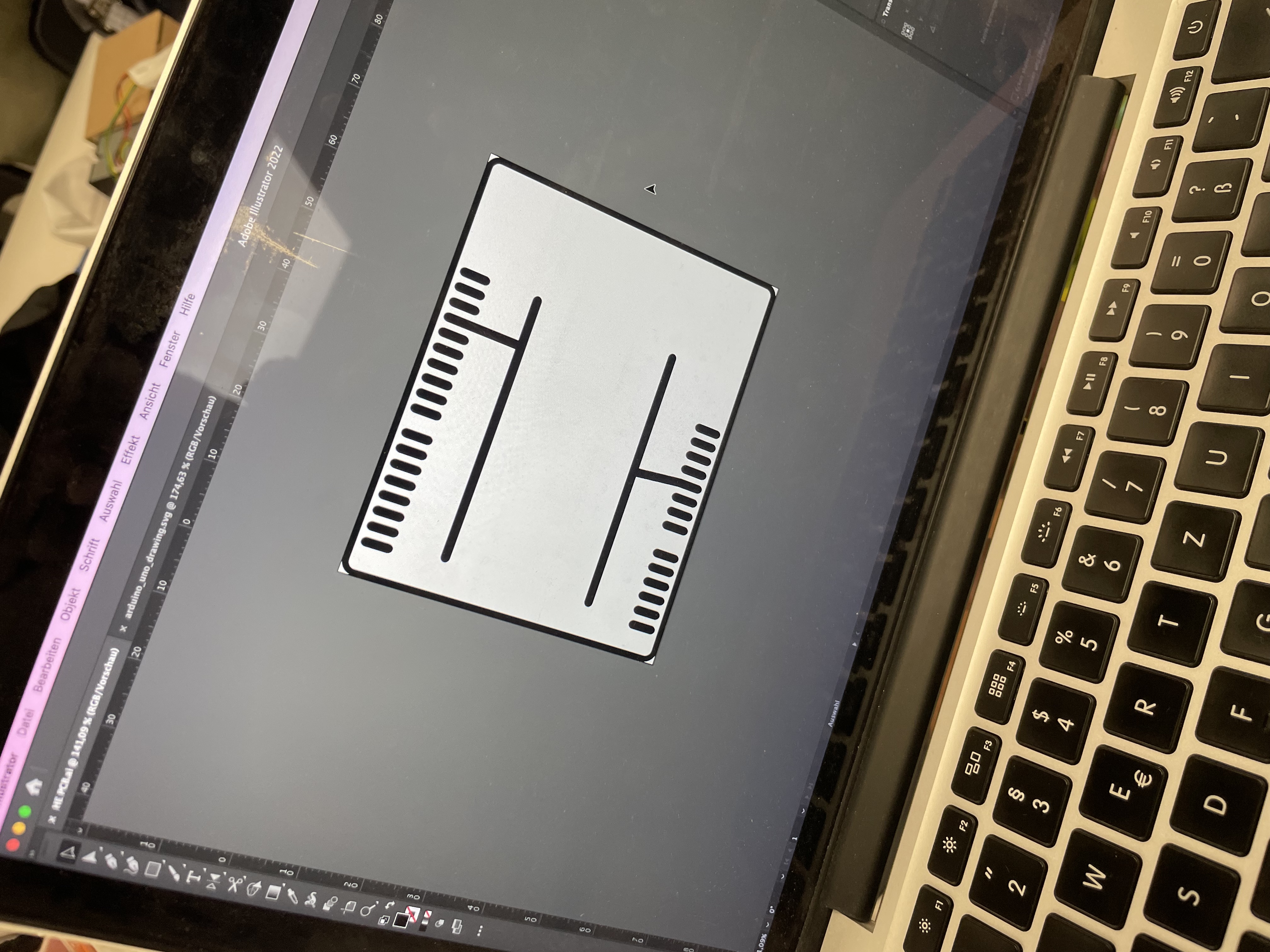
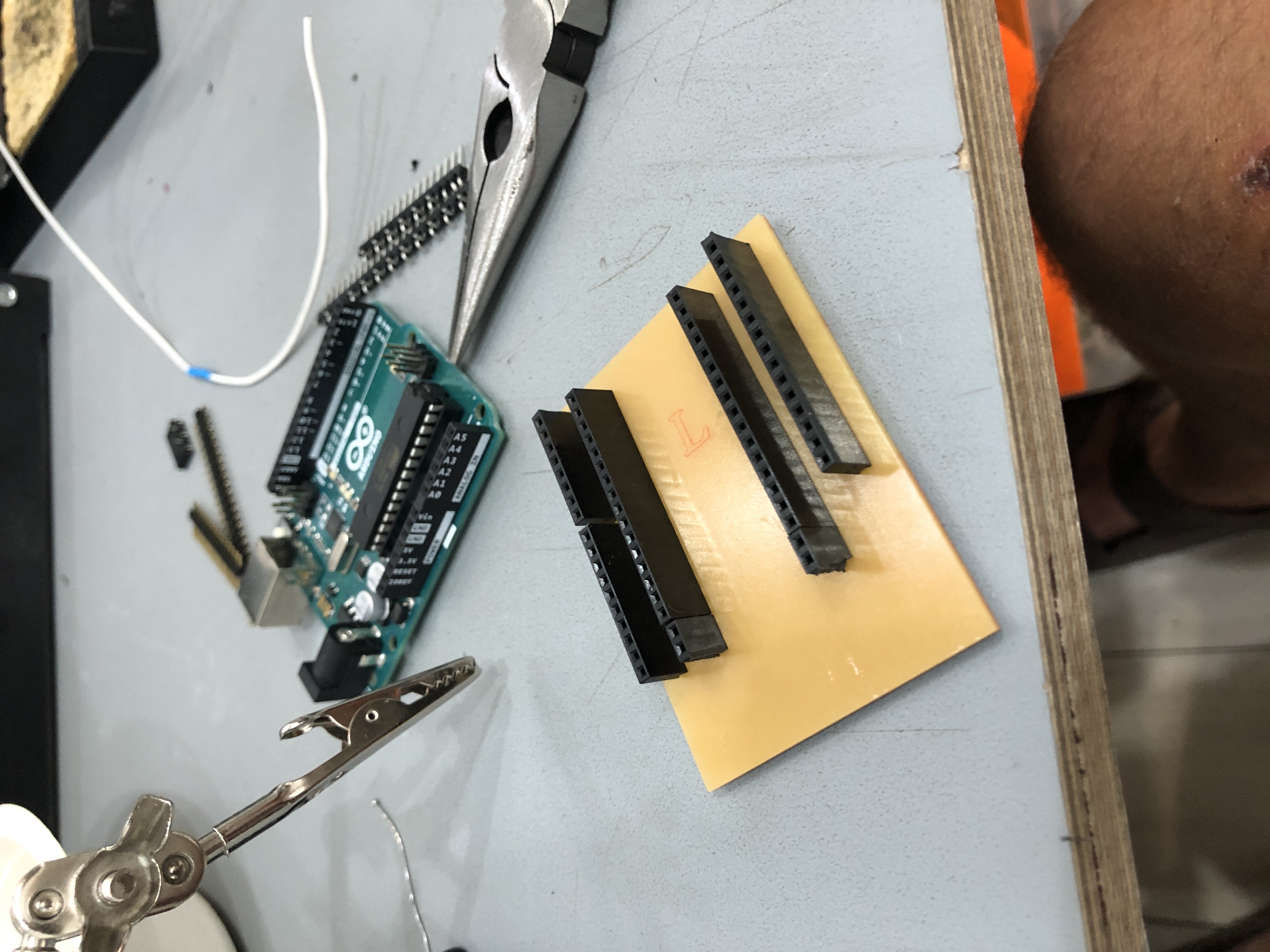
The first step was to have the measures of Arduino UNO board pins, to make the AI file, the two rows in the center are designed for ground and voltage, to enable to solder the female pins in there and don´t use the breadboard anymore and save a lot of cables.
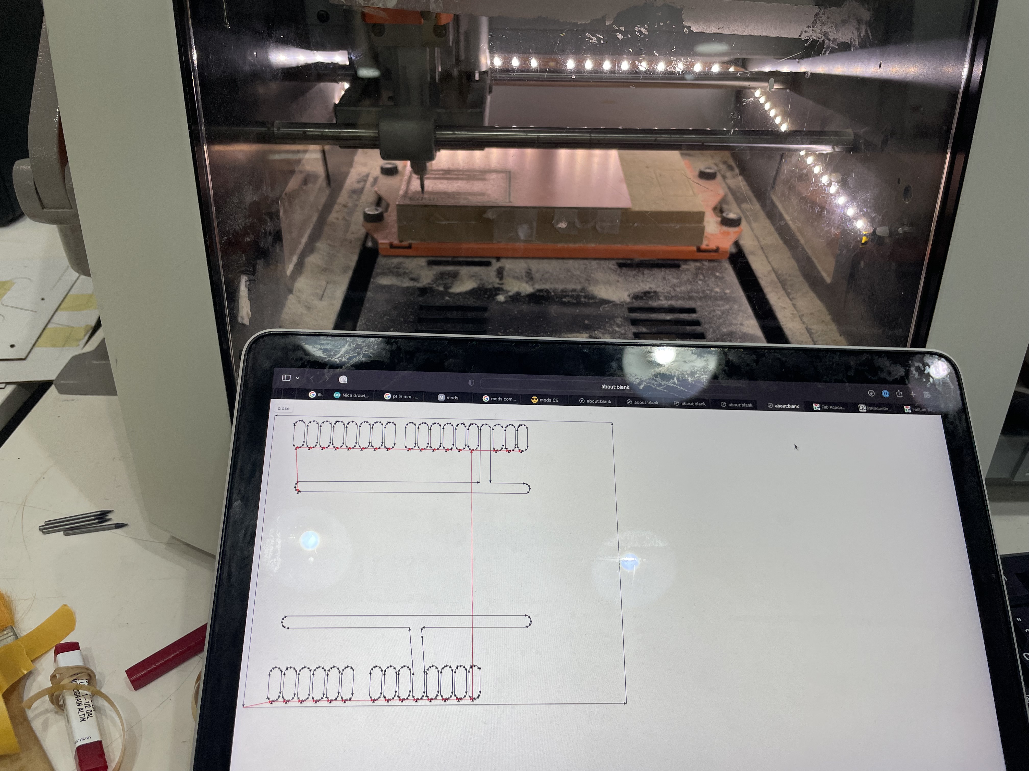
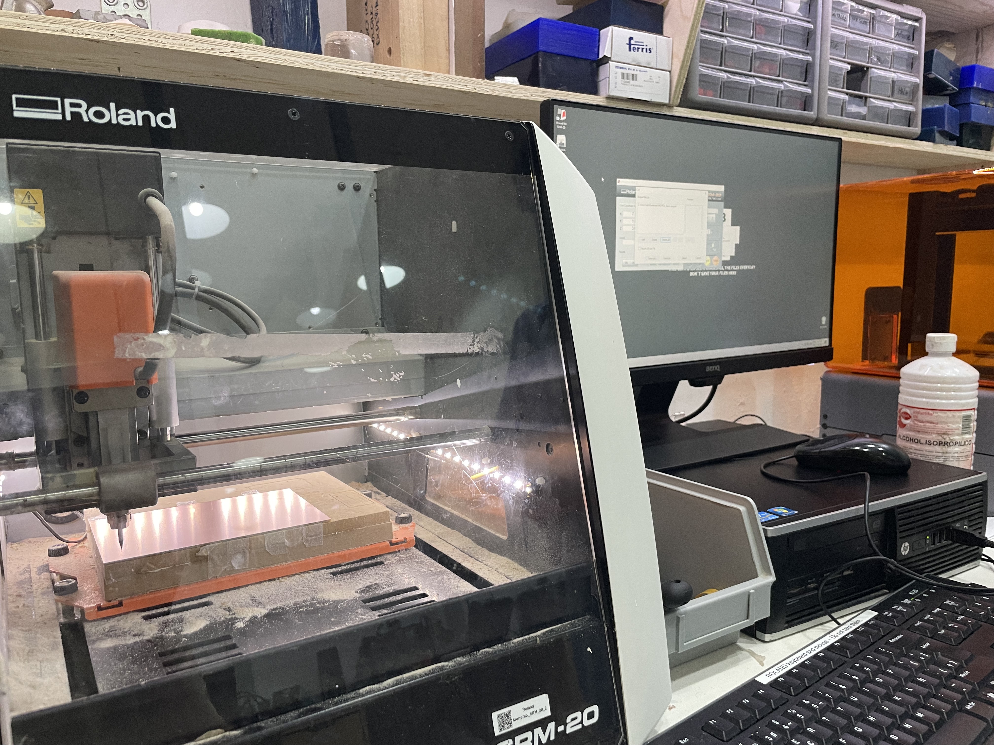
After that it was necesary to configure the gcode for the CNC machine to work, in this case were three gcodes, the first for the holes of the pins, then the “channels” of ground, voltage and pins, and finnaly the border of the PCB.
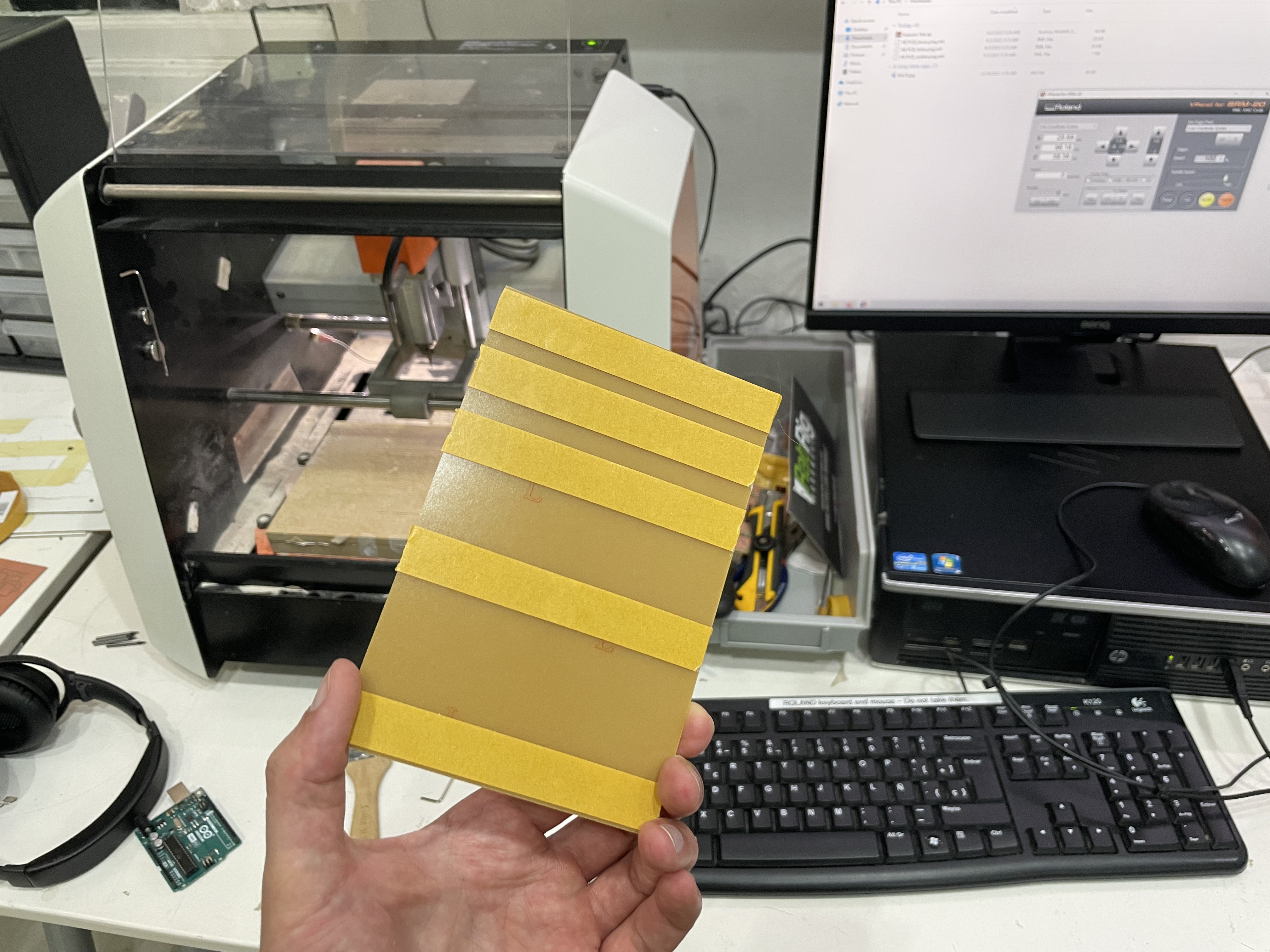
To attach the PCB to the machine, the double face masking tape is super useful, after it is cutted, it can be easy taken out with fingers or alcohol.
Having all settled up, its mandatory to fix the origin of the machine, including the Z axis, that is determined by the position and hight of the PBC.
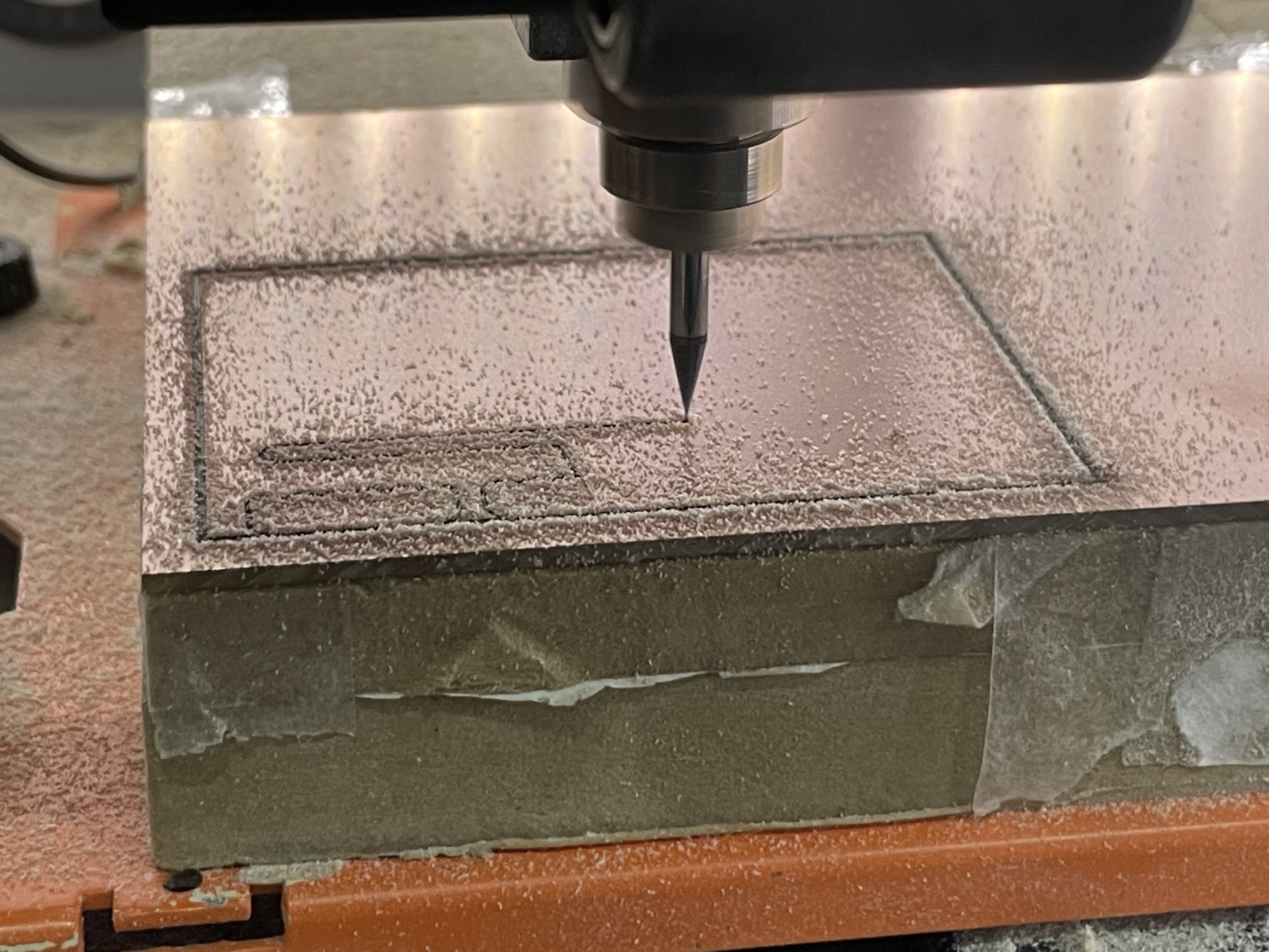
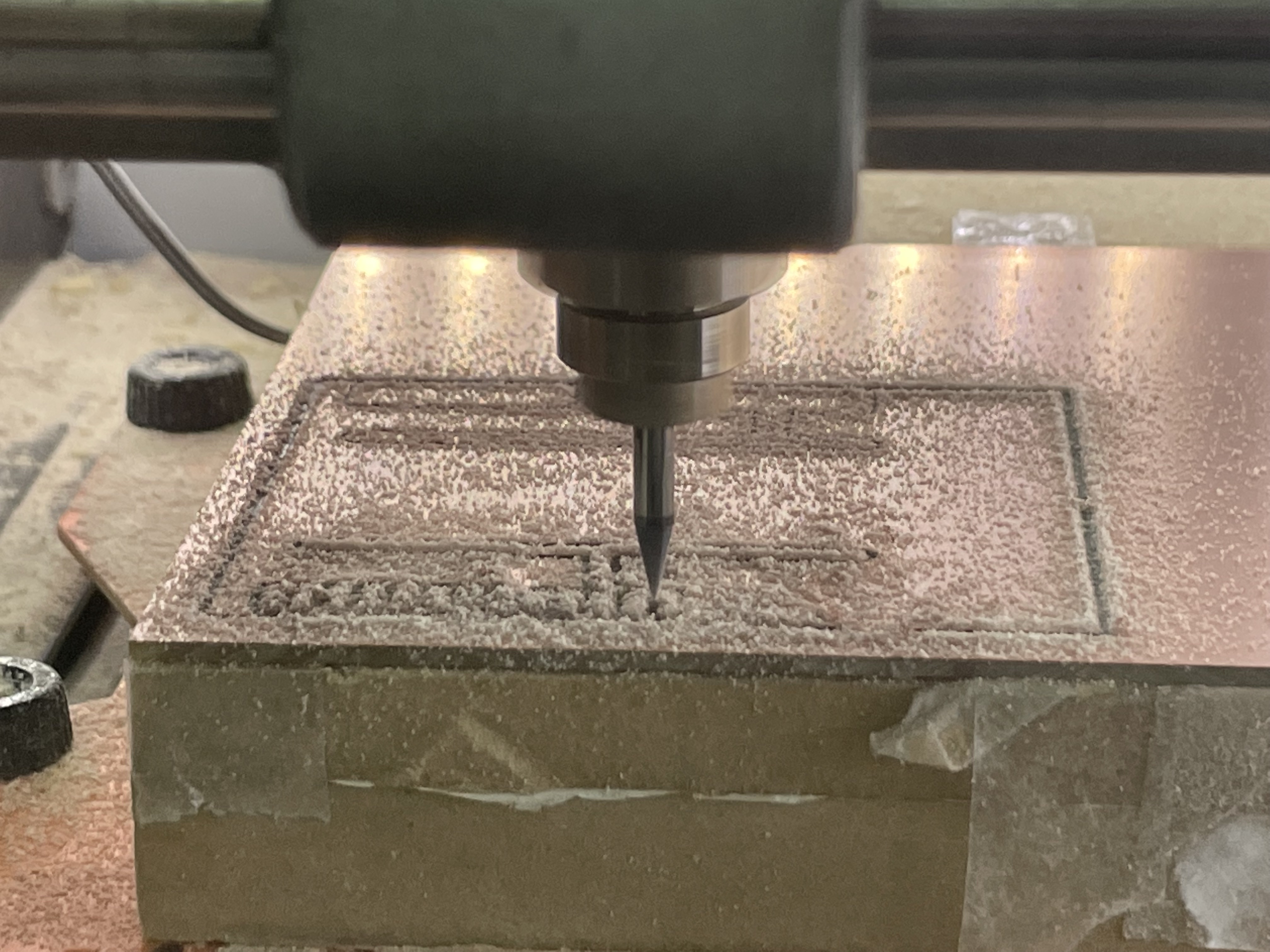
As the mill is super thin and fragile, its recomendable to keep watching the process till its almost finished, Also, the dust material that is cutted, gives a hint if the machine is cutting or not.
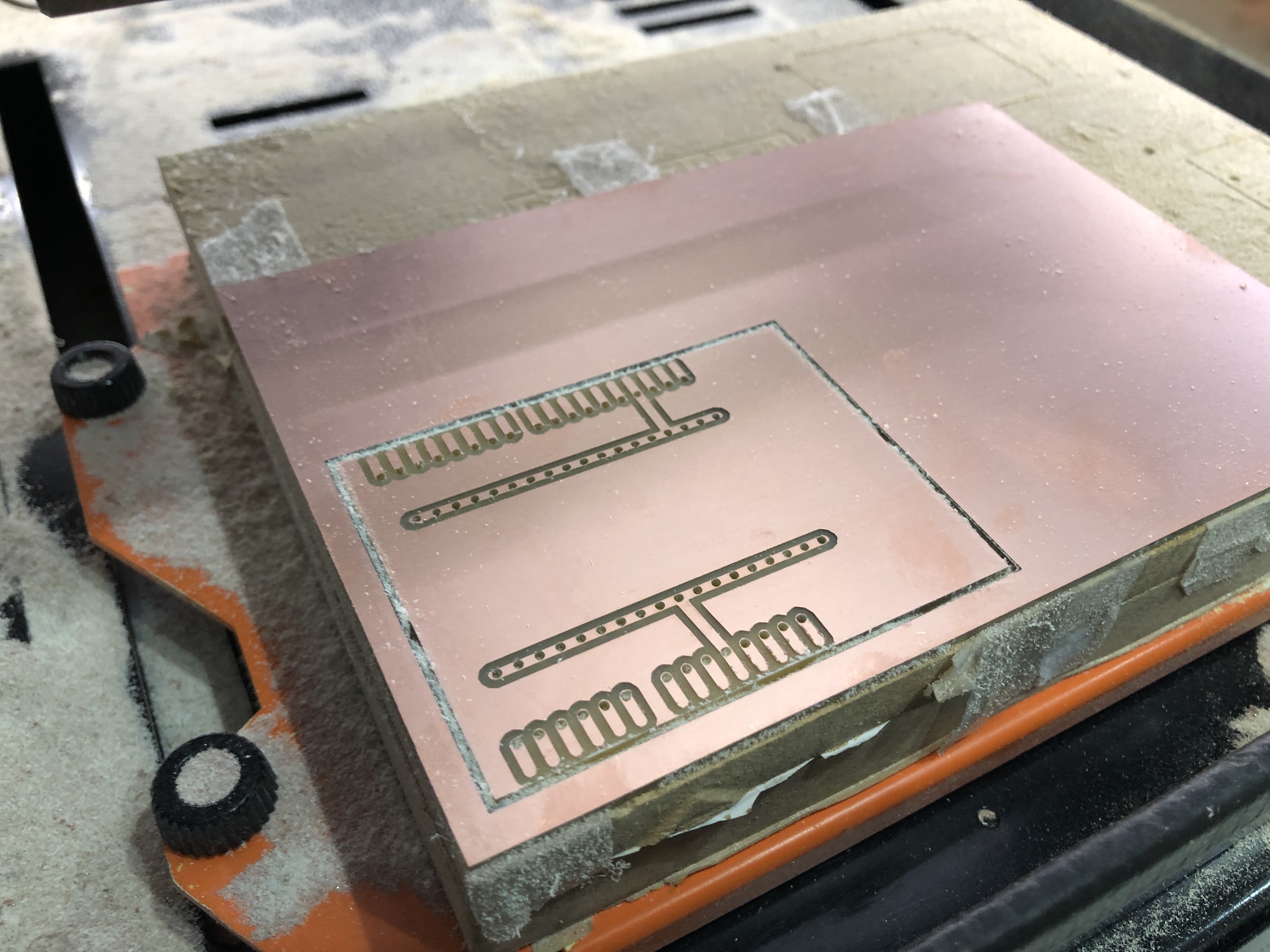
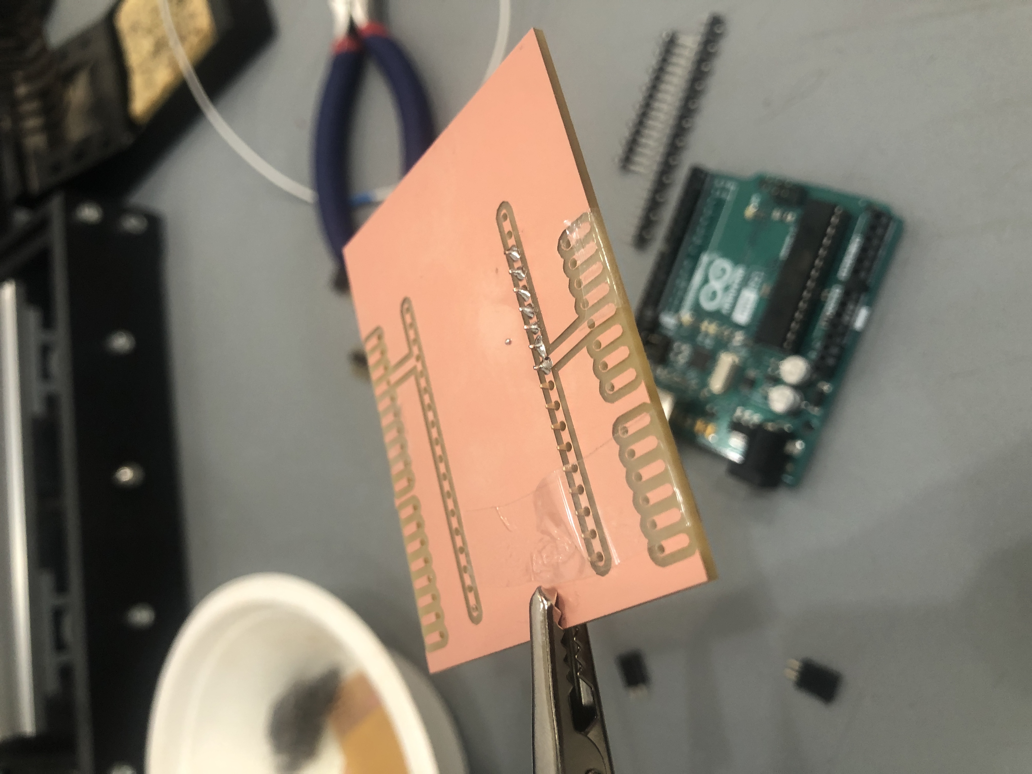
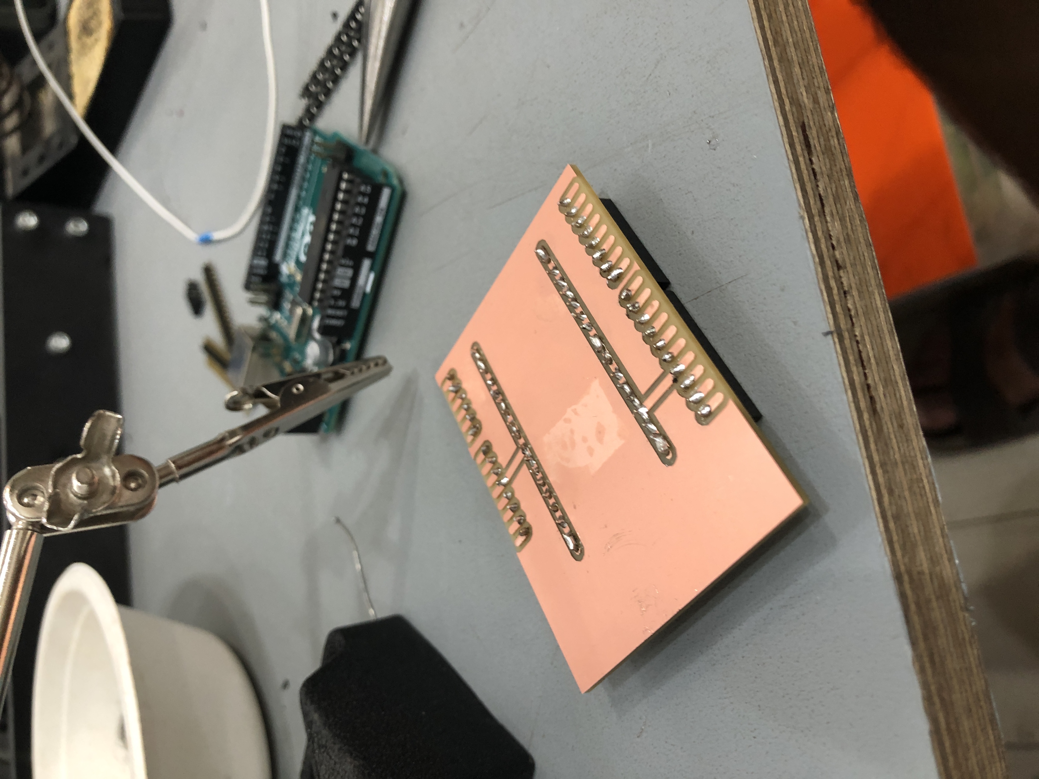
This is the result of the PCB cutted, with the holes, spaces for pins and profile, it is also mandatory to check first if it did all the cuts through, because if not, it is possible to send the file again, but if the PCB is moved, it is very difficult to match the origin again.
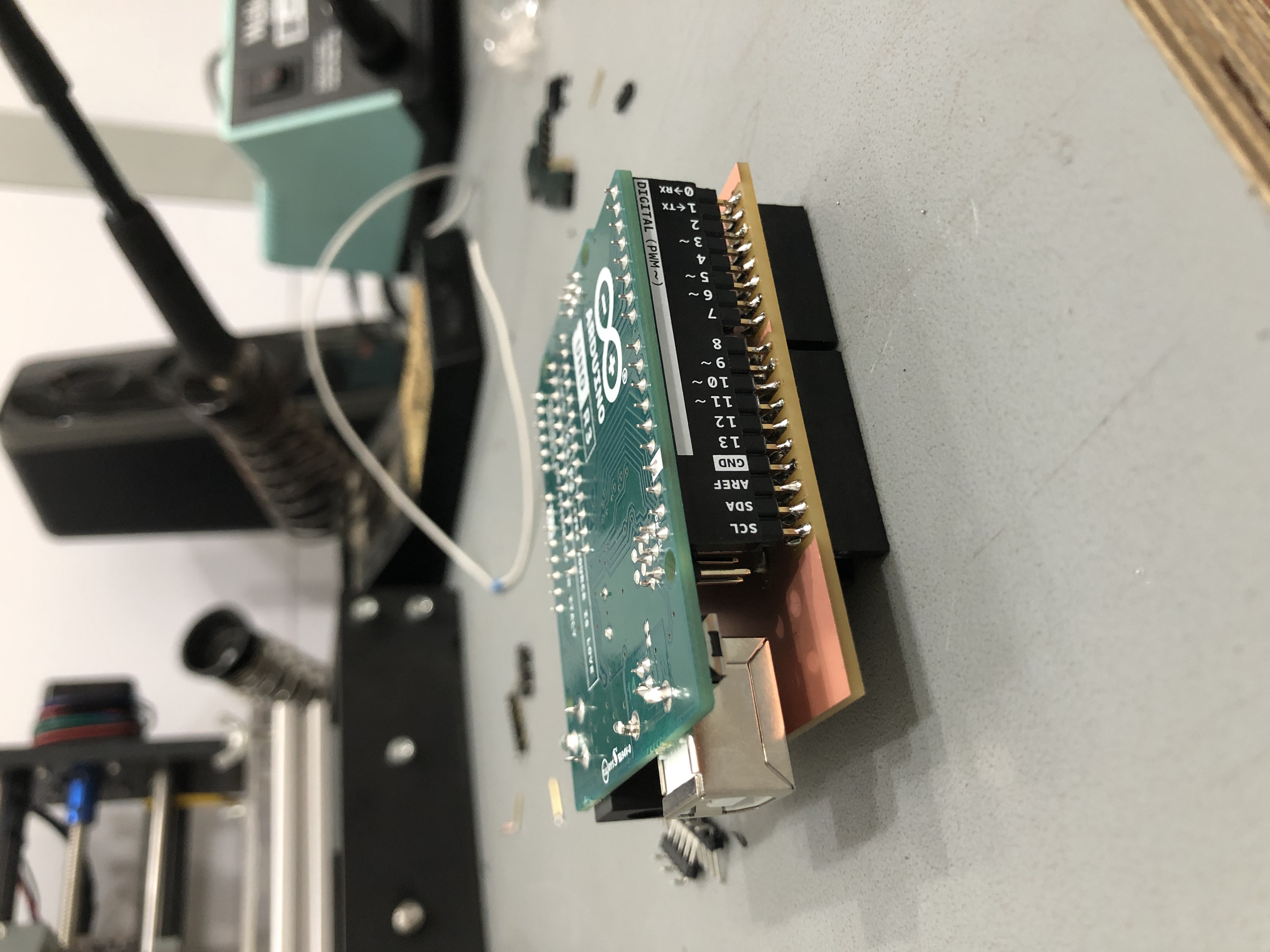
The shield was solder after and it fits perfect with the Arduino UNO. See WT 4 to see soldering process and configuration.
Soldering
We needed to have all of the pins available to connect preassure sensors, buttons and potentiometers, so we also did two channels for 5v and ground.

For the first step, It was necesarry to solder female pins, that share the Arduino UNO distribution,also it was necesarry to cut some rows to reach the number of pins needed.
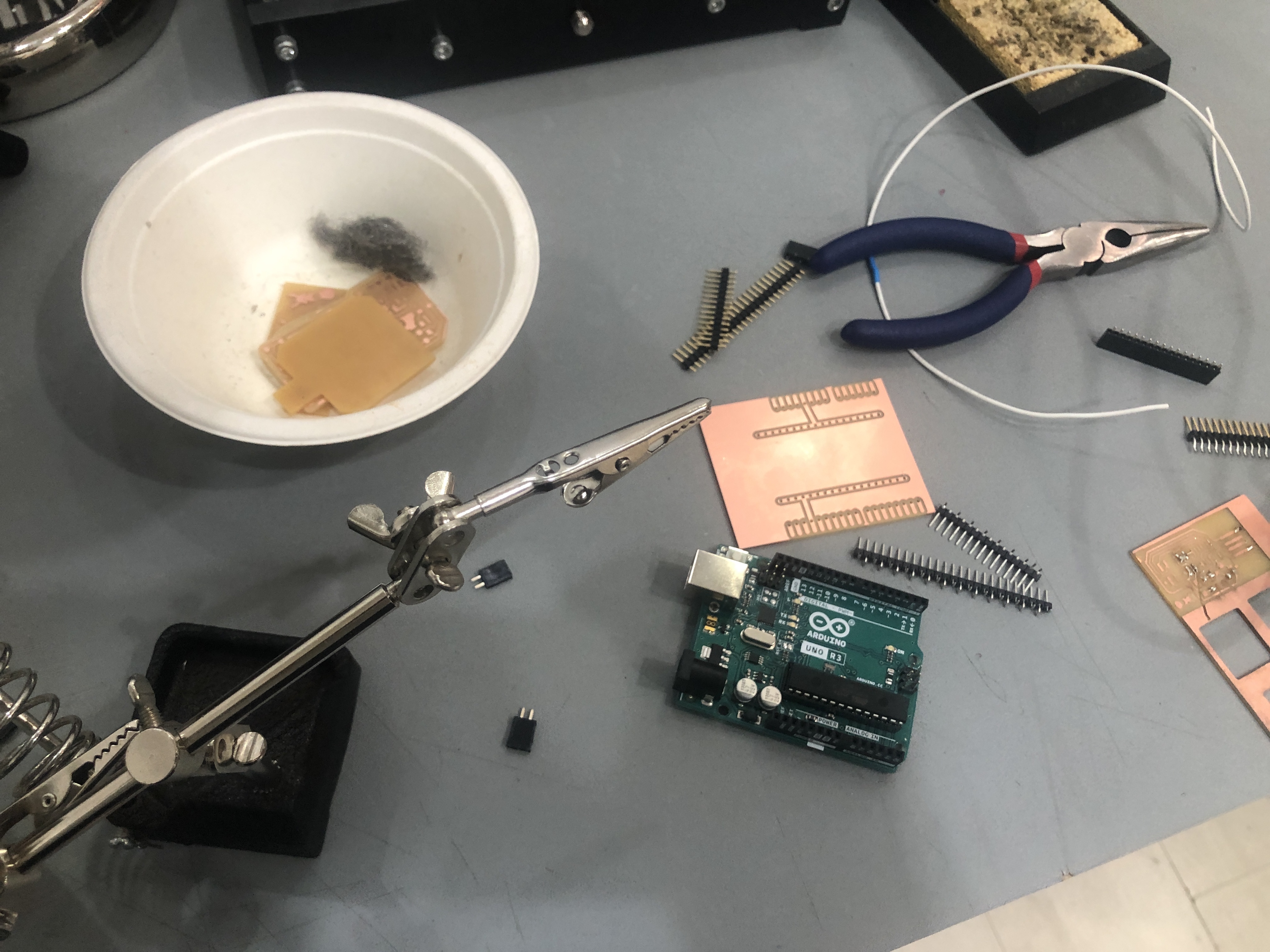
The tool that grab objects like a tweeser, was very usefull for soldering, because it kept the board steady, to use both hands to grab the soldering material and the solder tool
The soldering of pins becomes mechanical after some attempts, so in a couple of minutes the four row of pins was ready.
The challenge in this board, was to solder the male pins that plug the Arduino, because we made the space for the solder but with no holes, so the pins had to be perpendicular to the board, it is not the best solution, because after some movement its possible to break the soldering easy. But fir the prototype purposal, it works pretty good.
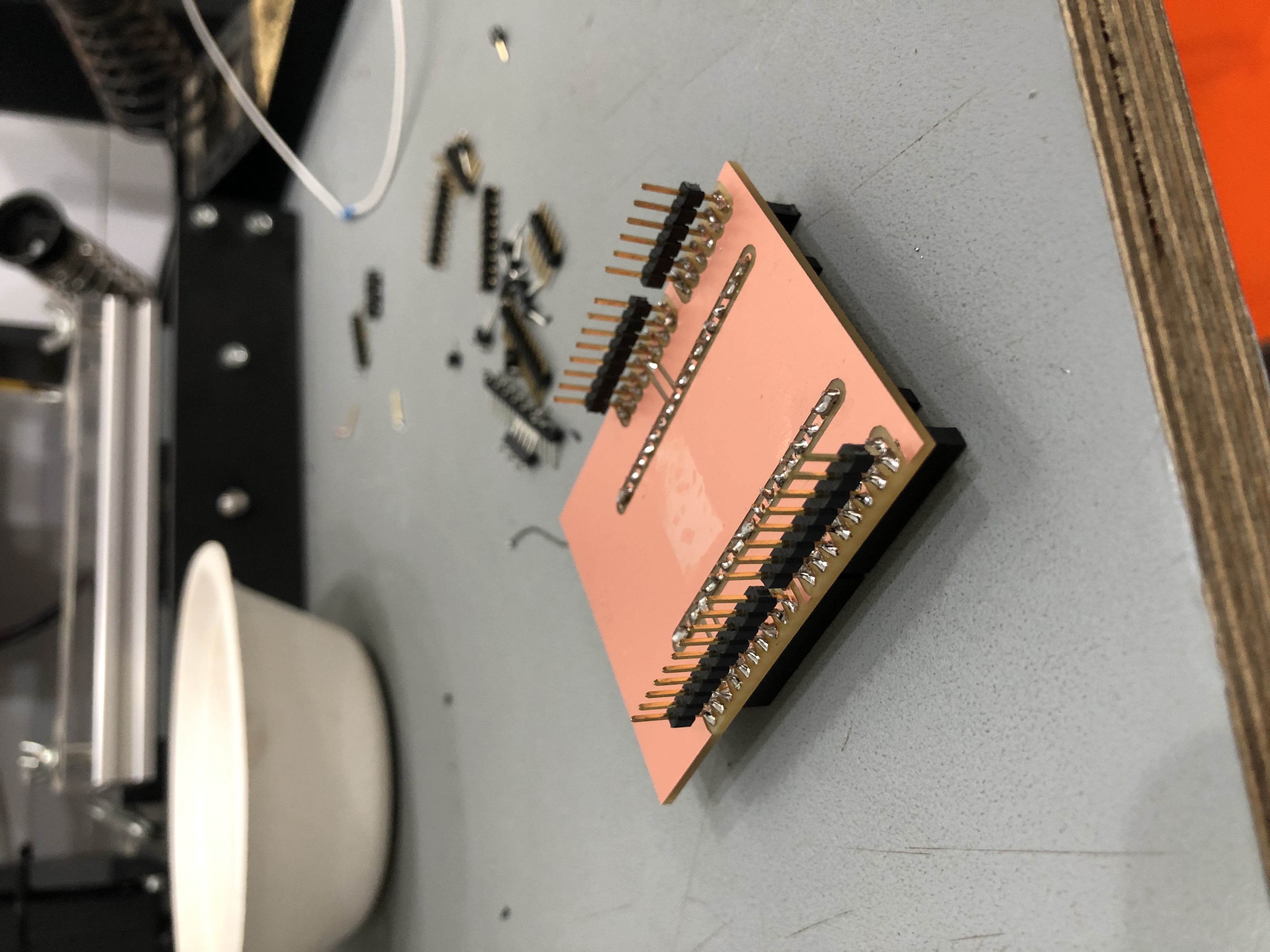
To solder this pins, it was easy firts to had the arduino plugged, and then solder the pins to the board.it ensure a correct display of the pins.

After the soldering, we manage to try all the pins, with the arduino connected to the computer, having sucess because they all worked fine.
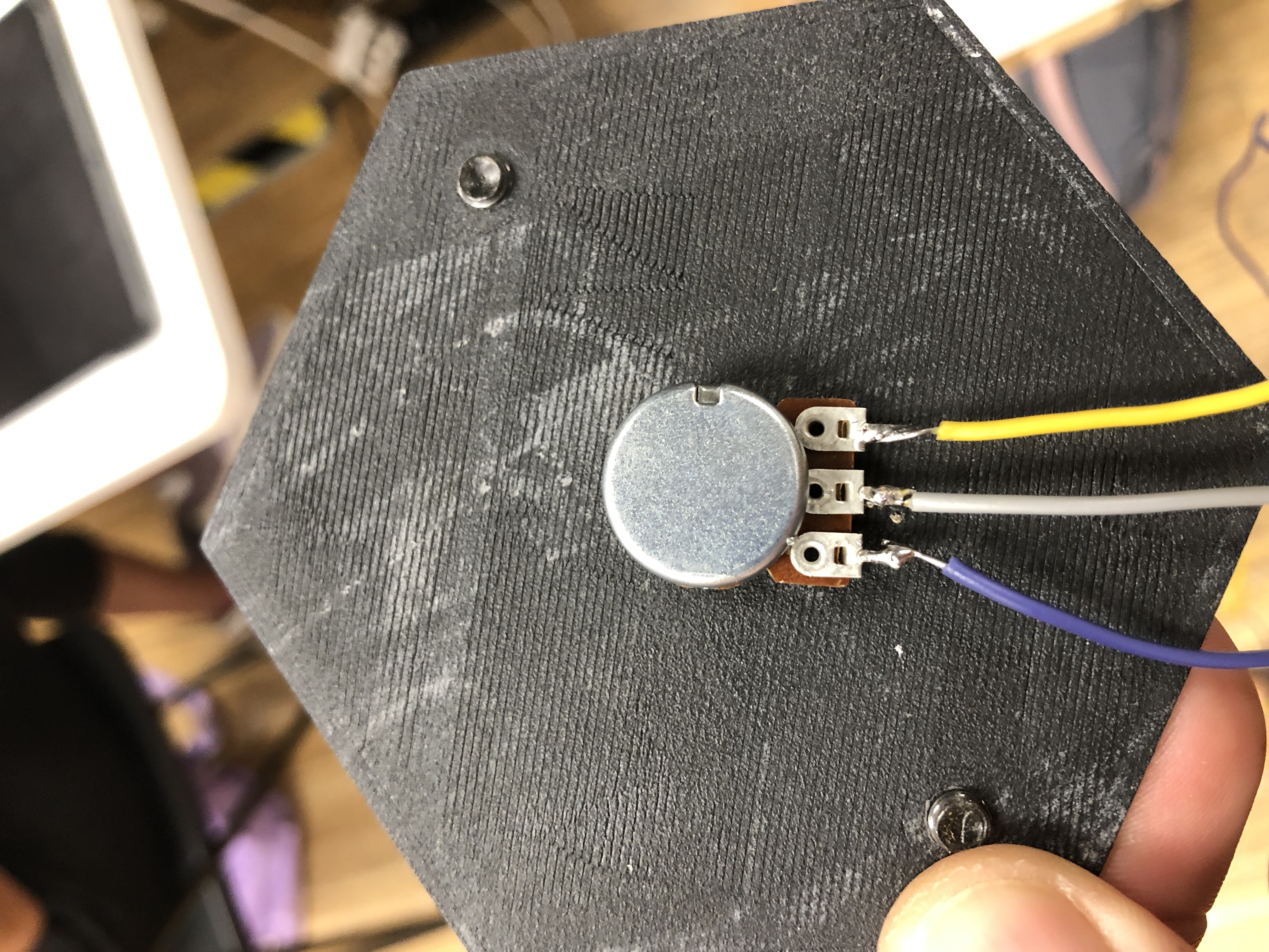
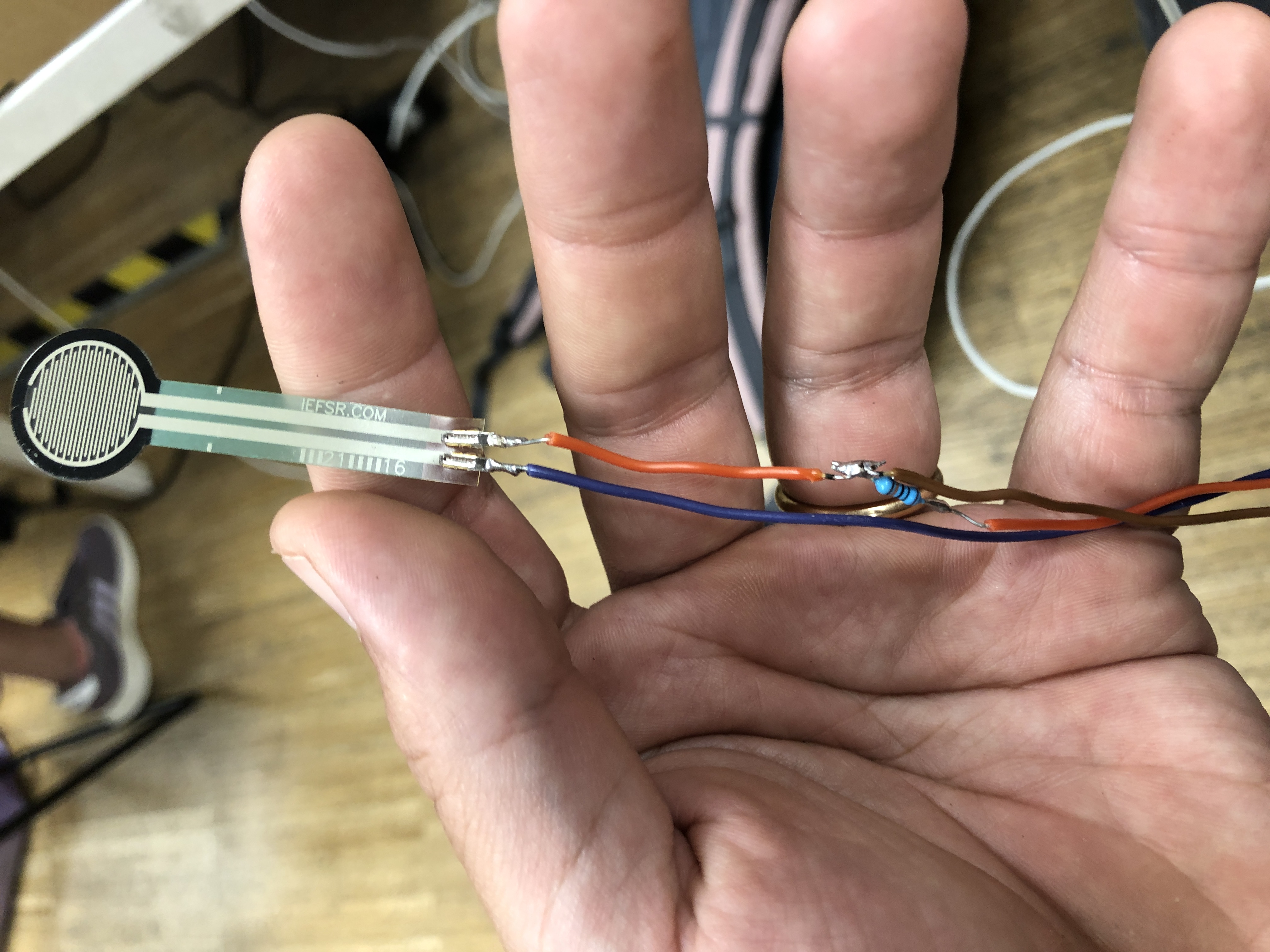
Then we soldered both potentiometer and preassure sensor. The preassure sensor was a bit tricky, because it was necessary to have a resistance in between cables, to avoid shortcircuits, we soldered the resistancefar away from the sensor.
Programing and testing
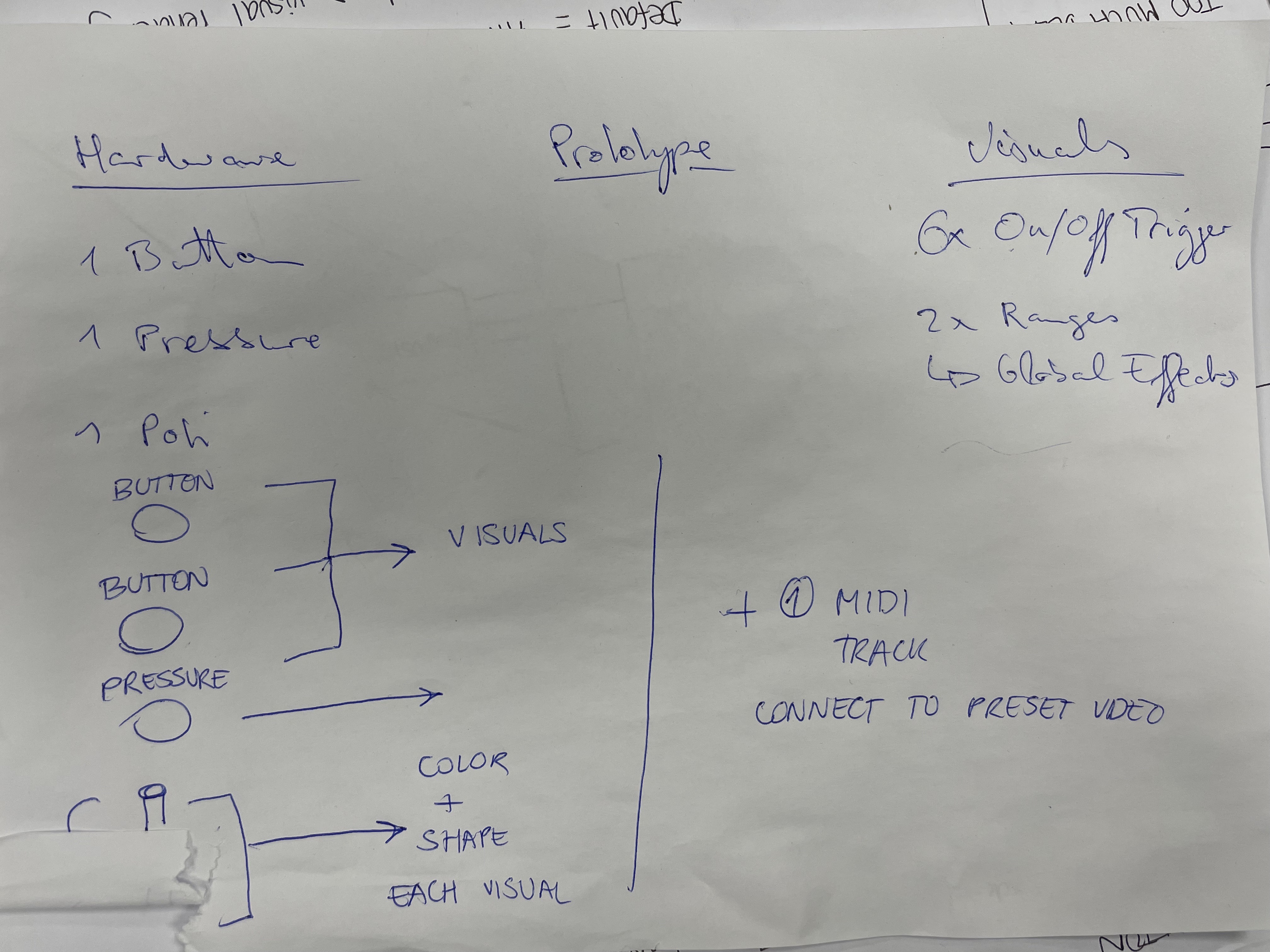
For making the PBC work, we made a diagram to understand the connections and what we need for making the controllers to work
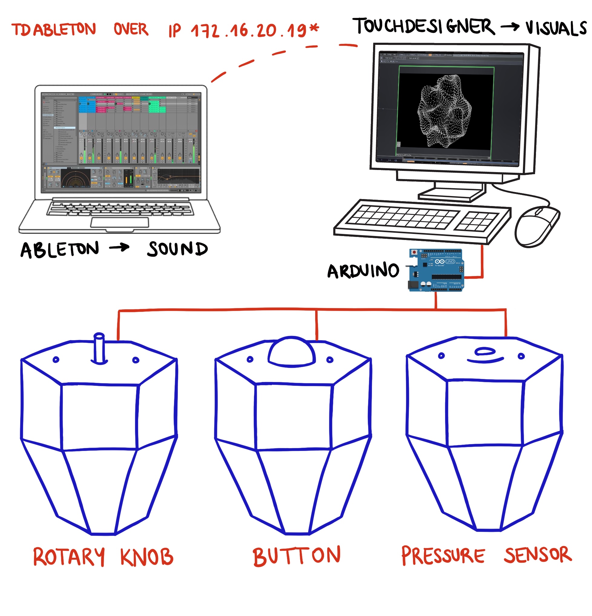
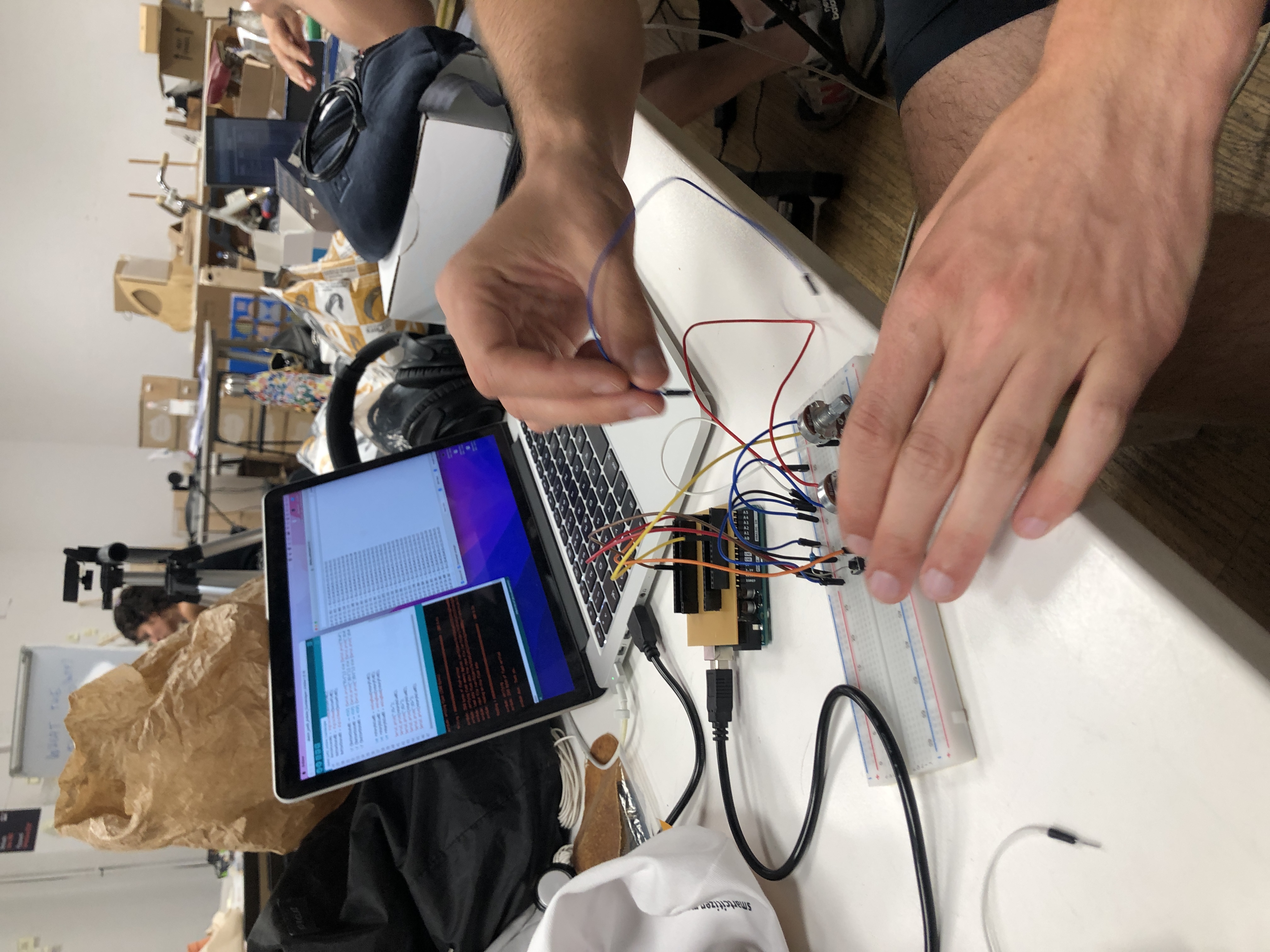
For the hardware testing, we connected one button, one potentiometer, and one preassure sensor, using the biomaterial and 3d printed lids to make everything to work.
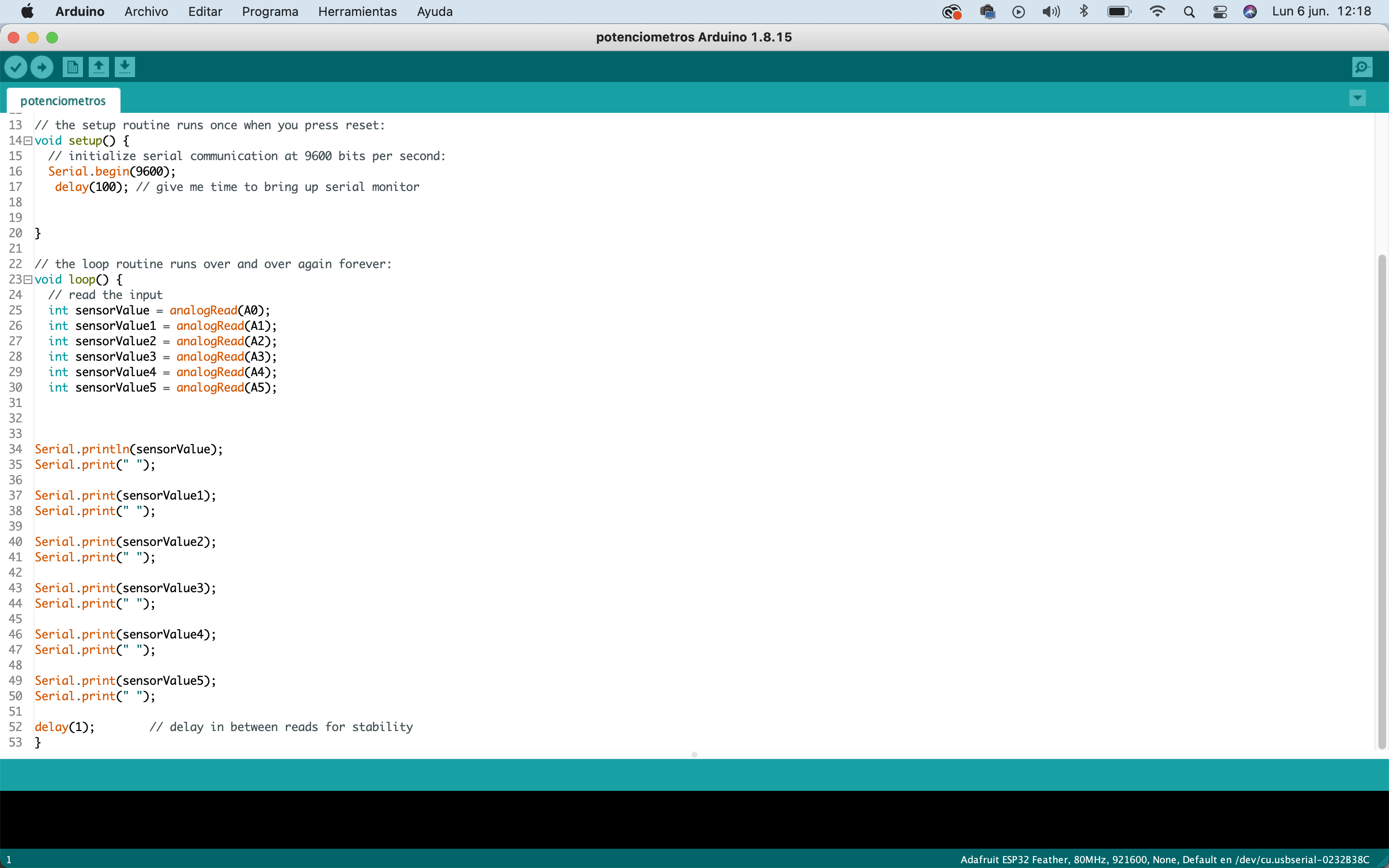
The Arduino program is quite simple, it just for reading sensor values to use them with touchdesigner and Ableton.