Week6
Week 6
Week 6
Design a PCB board also called breakout-board for your ESP32 HUZZAH 32 microcontrollers ( or other board that you want to use rapberri pi ,etc) that allows you to connect an input (sensor) or an output (actuator) to your commercial board without cables. Include the design files in your webpage and explain well the process on how you did it.
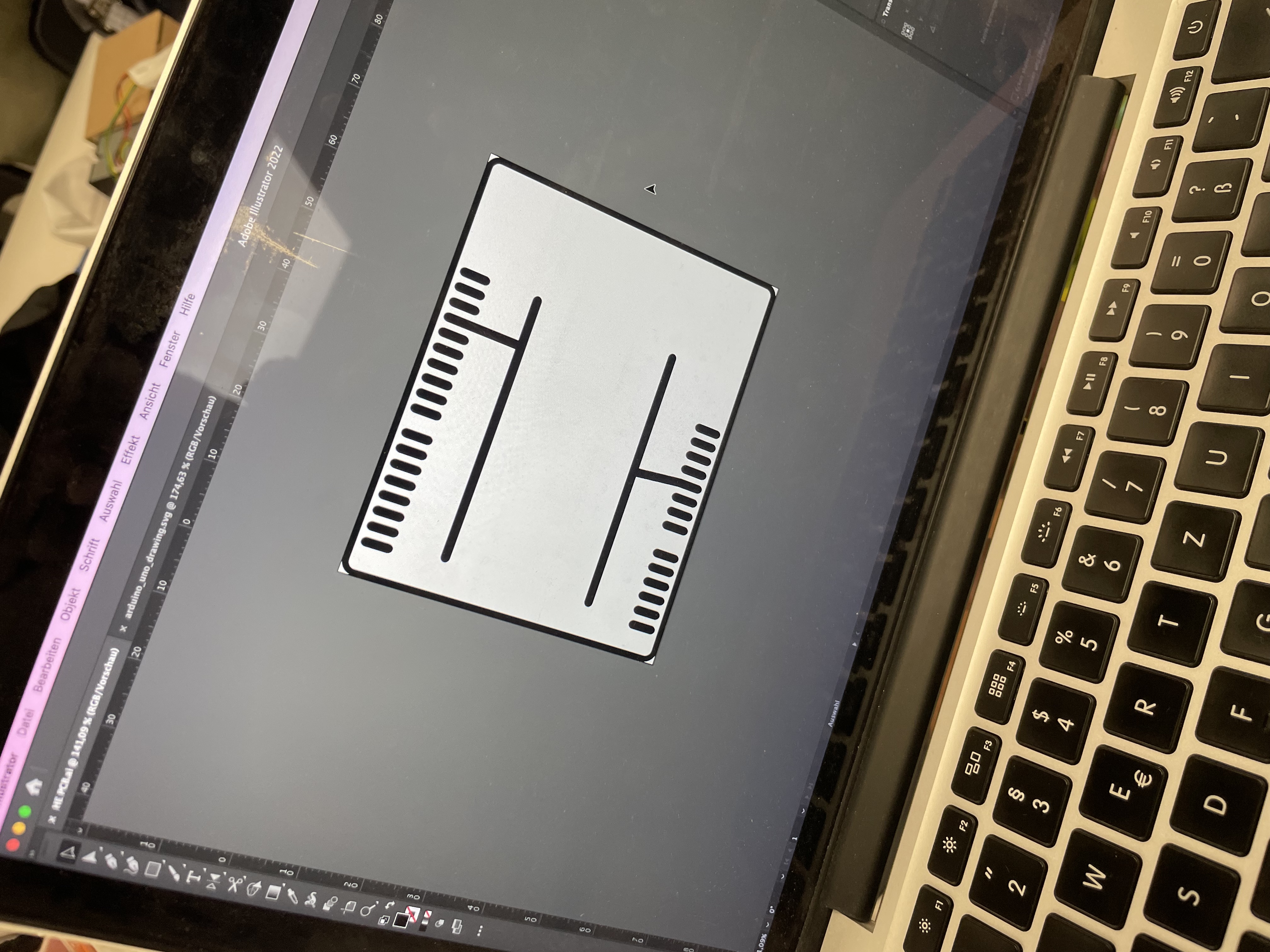
The first step was to have the measures of Arduino UNO board pins, to make the AI file, the two rows in the center are designed for ground and voltage, to enable to solder the female pins in there and don´t use the breadboard anymore and save a lot of cables.
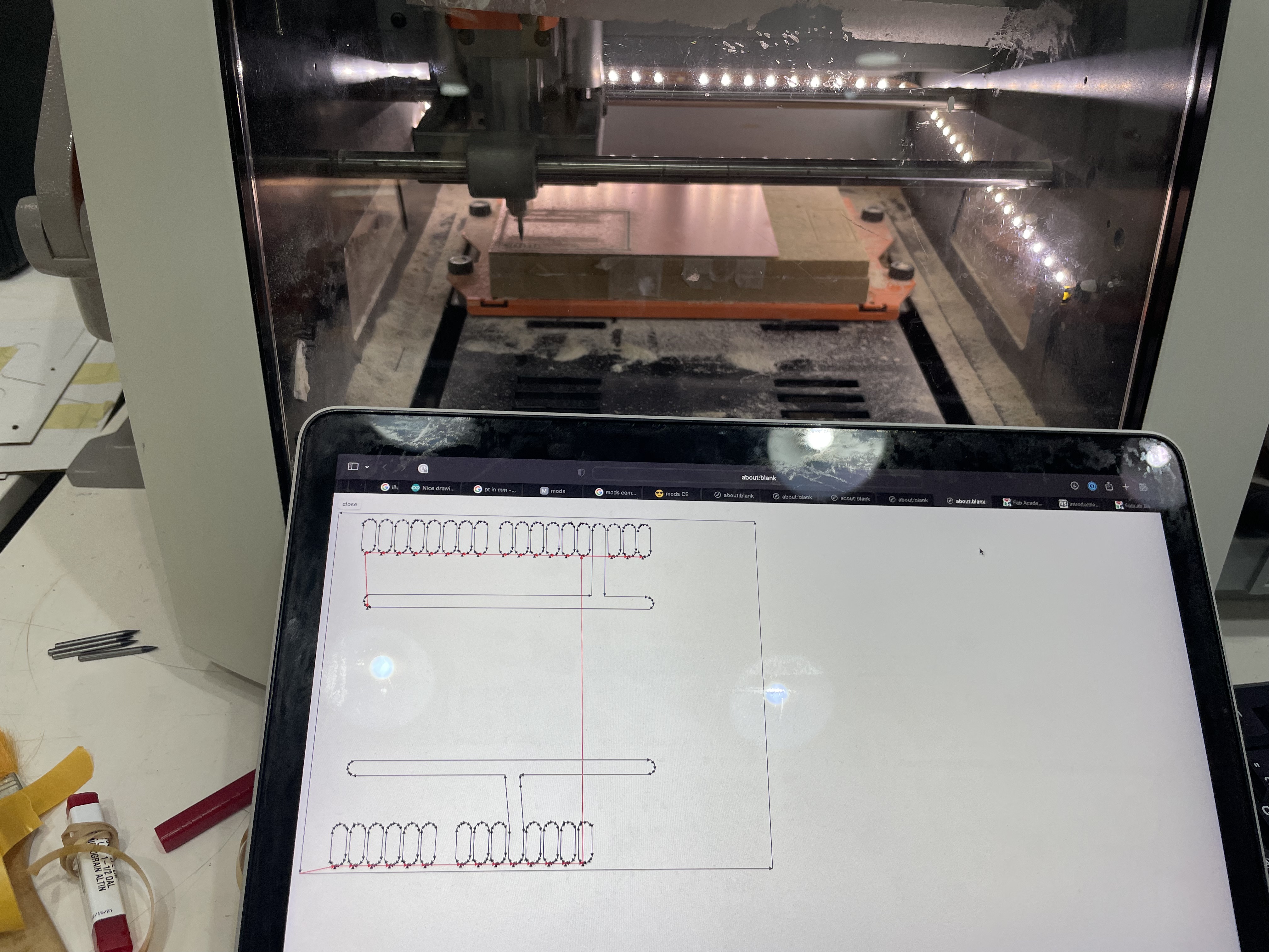
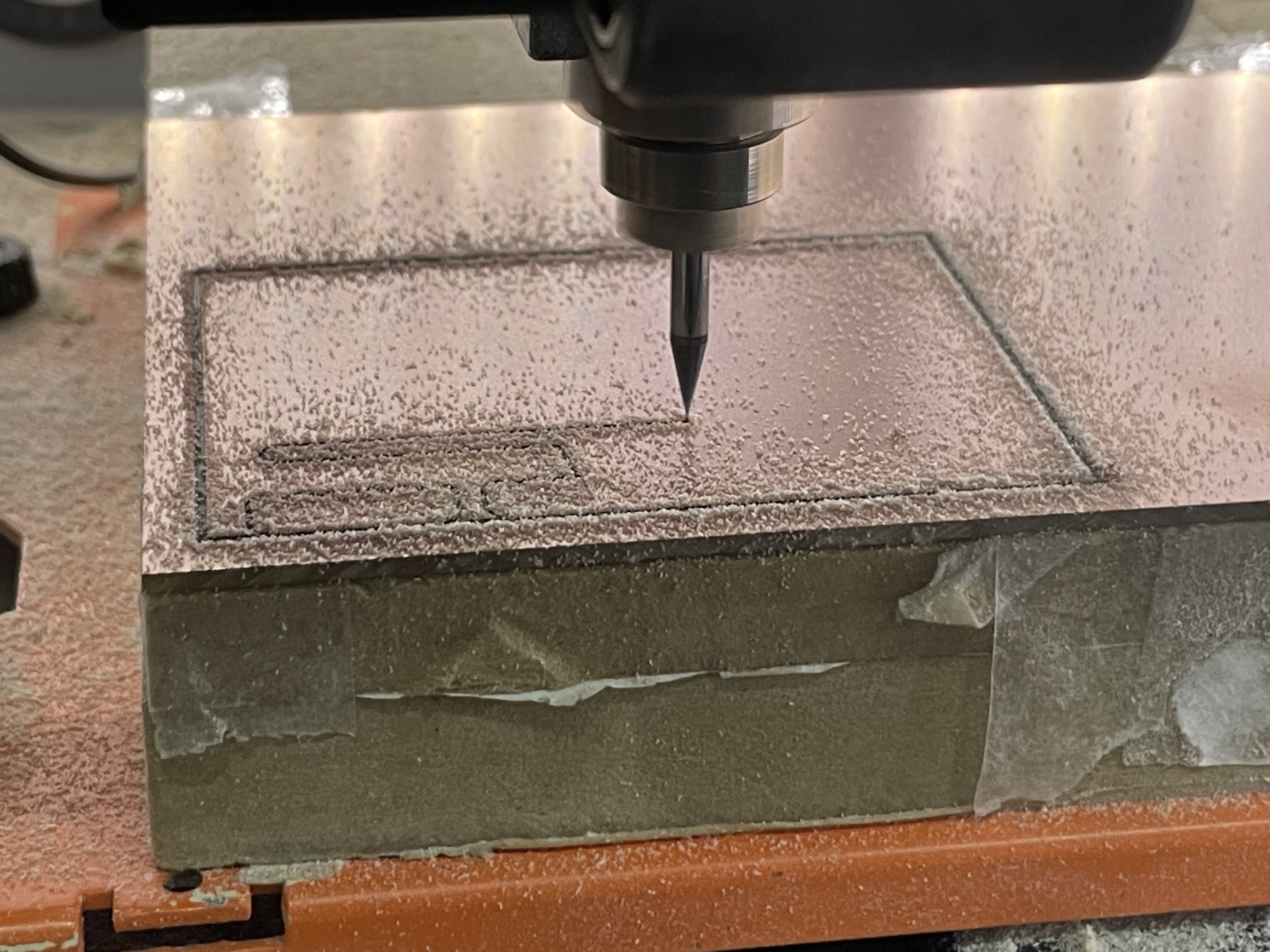
After that it was necesary to configure the gcode for the CNC machine to work, in this case were three gcodes, the first for the holes of the pins, then the “channels” of ground, voltage and pins, and finnaly the border of the PCB.
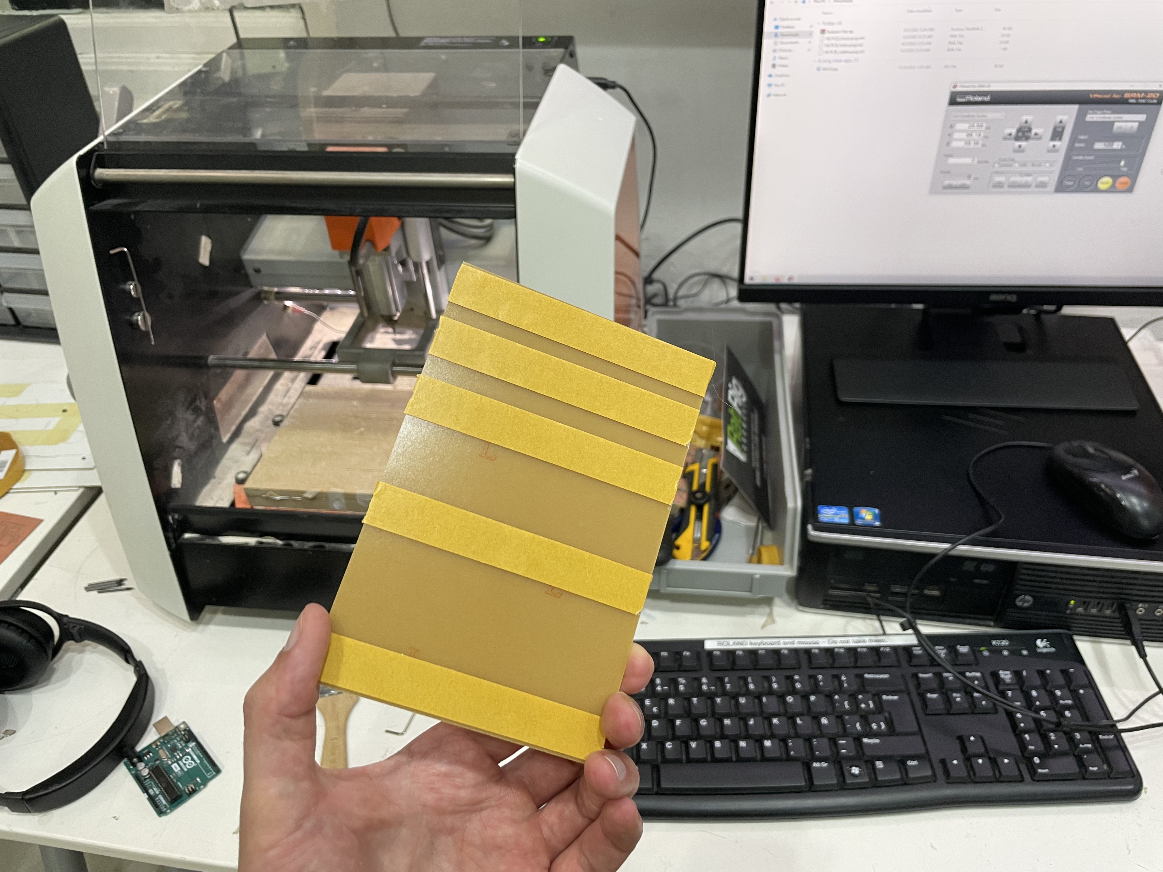
To attach the PCB to the machine, the double face masking tape is super useful, after it is cutted, it can be easy taken out with fingers or alcohol.
Having all settled up, its mandatory to fix the origin of the machine, including the Z axis, that is determined by the position and hight of the PBC.
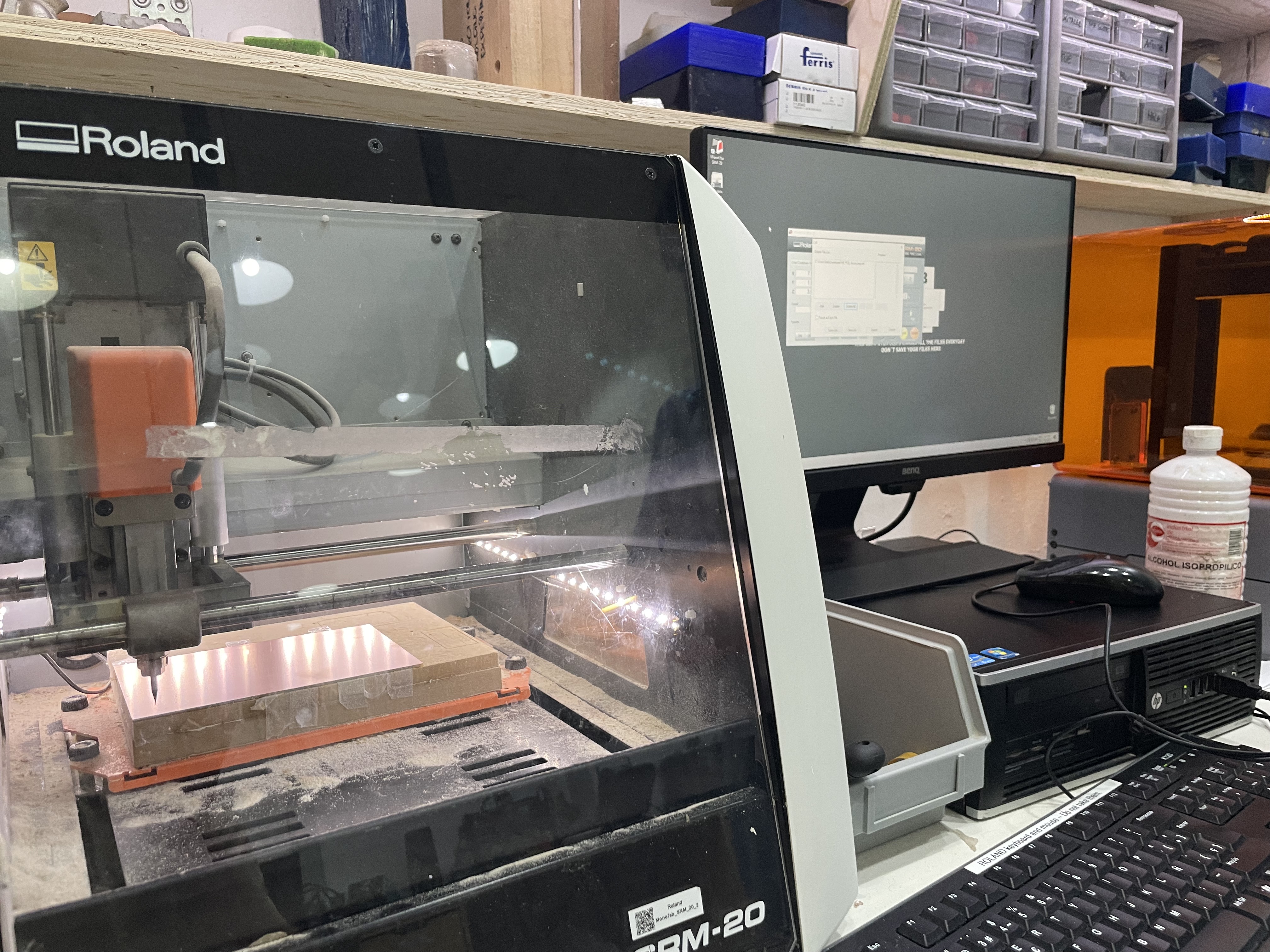
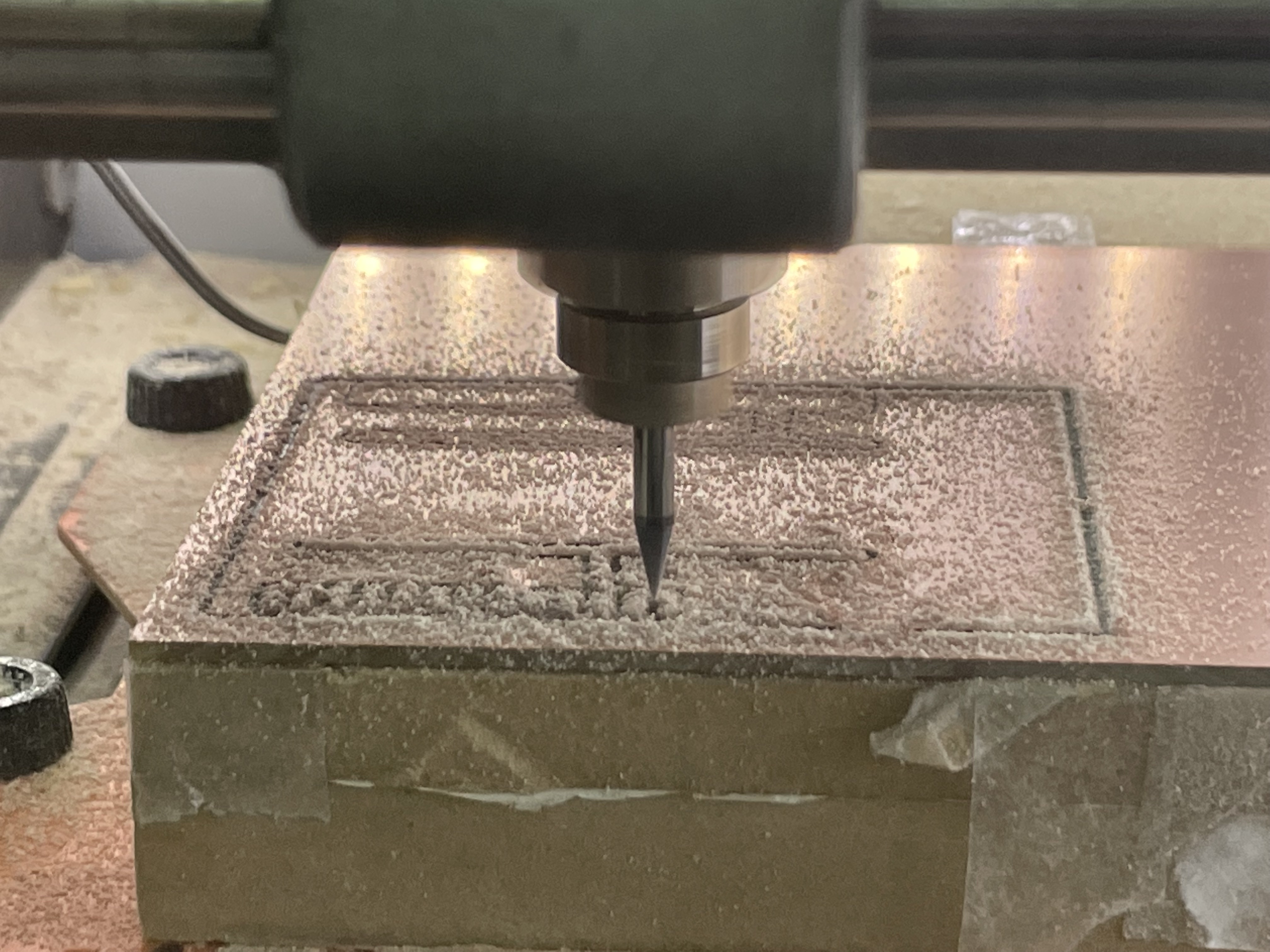
As the mill is super thin and fragile, its recomendable to keep watching the process till its almost finished, Also, the dust material that is cutted, gives a hint if the machine is cutting or not.
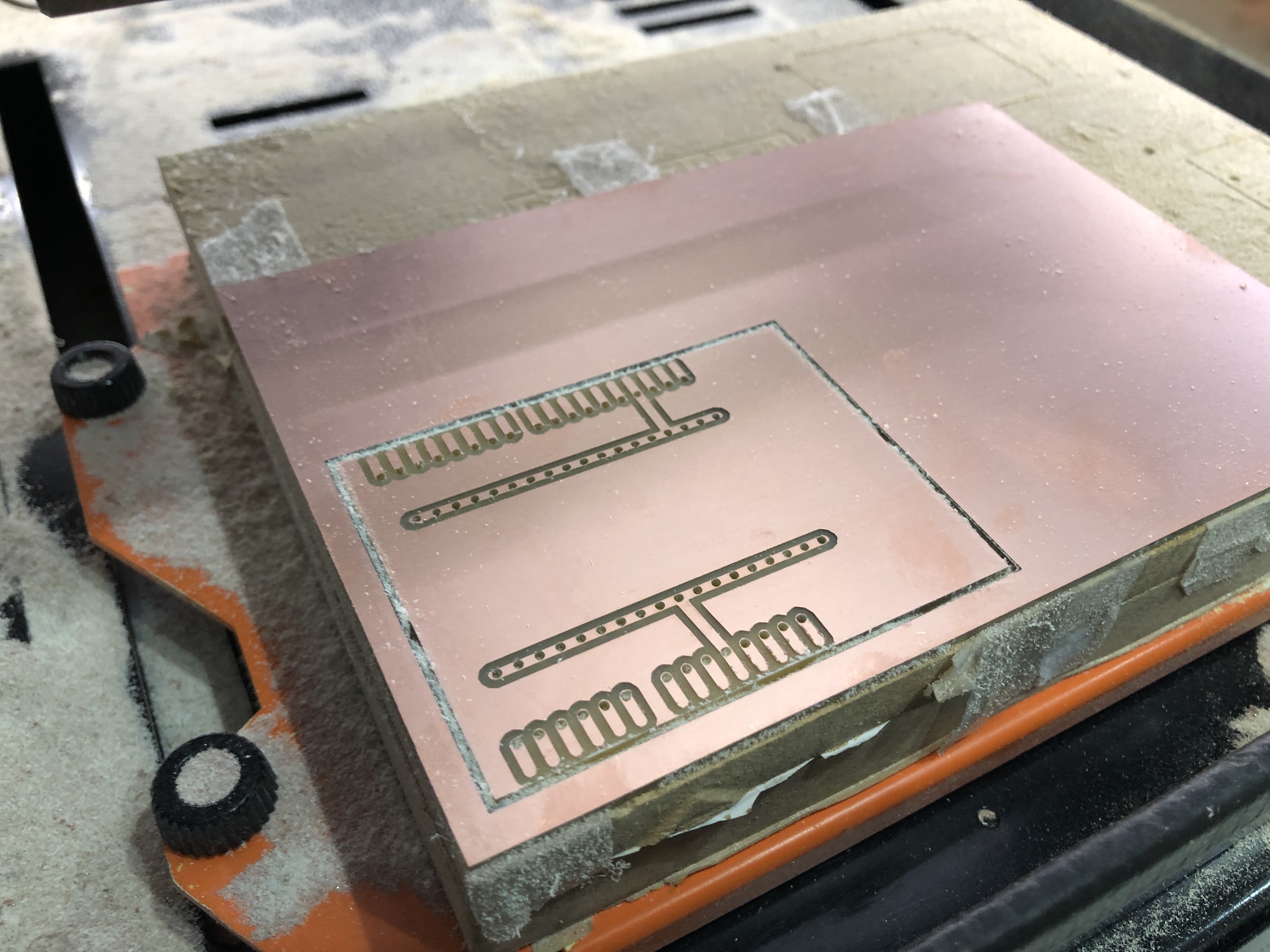
This is the result of the PCB cutted, with the holes, spaces for pins and profile, it is also mandatory to check first if it did all the cuts through, because if not, it is possible to send the file again, but if the PCB is moved, it is very difficult to match the origin again.
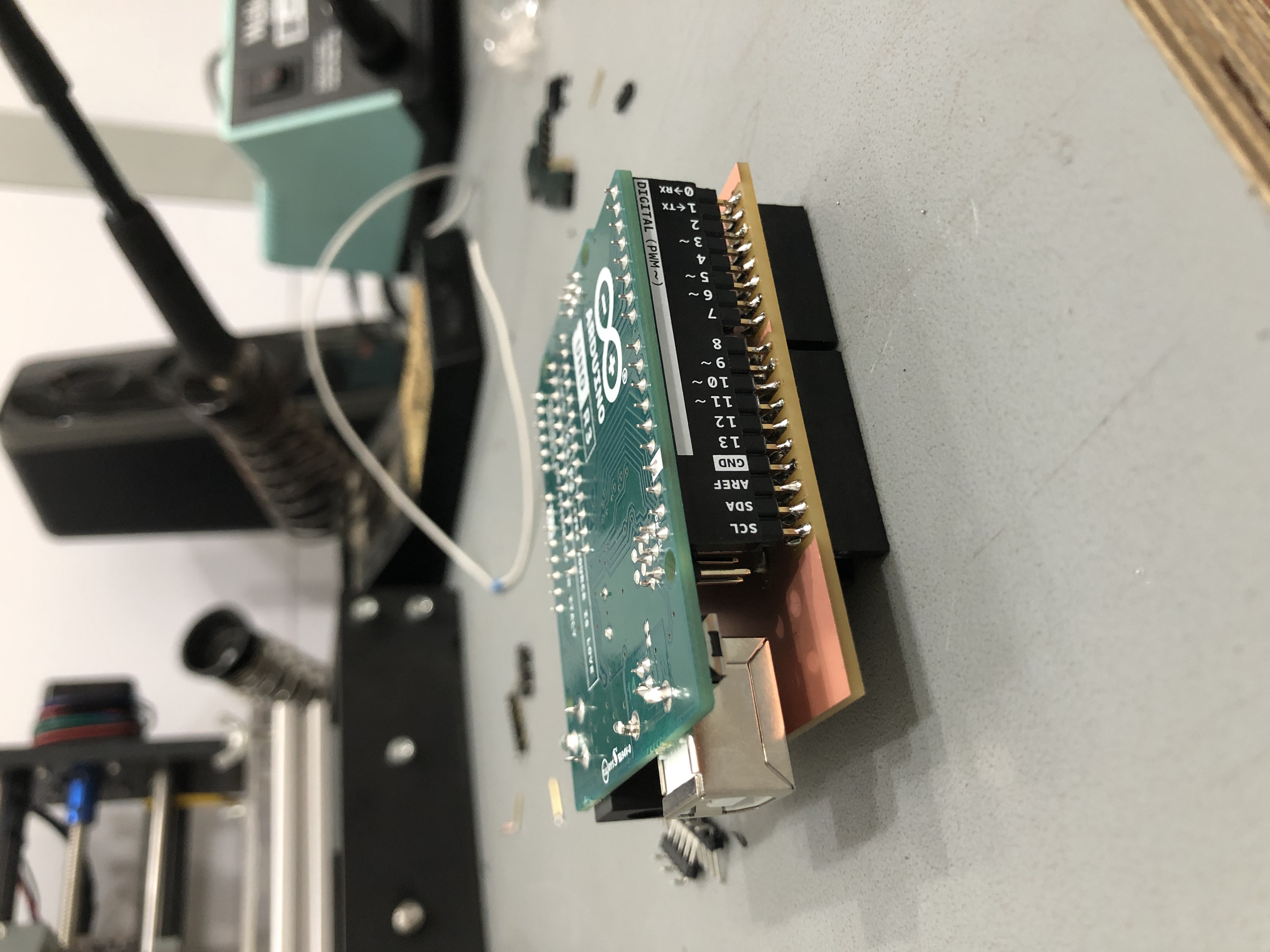
The shield was solder after and it fits perfect with the Arduino UNO. See WT 4 to see soldering process and configuration.